Motivation
In this post, I will run through the construction of a 30A 125V smart plug based on the ESP32 platform that can be either controlled from a simple webpage, or integrated into a system like Home Assistant.
While there are many good commercial options for smart plugs for home devices, and there are many industrial options for controlling heavy machinery, there’s a bit of a gap in the market for easy to use smart plugs for more heavy-duty workloads. By “heavy-duty” here, I mean larger than 15A @ 125V to be switched. This is (likely) because the standard “three prong” plug (NEMA 5-15) is only rated for 15A. Devices with NEMA 5-20 or better may exist, but one of the loose design constraints here will be supporting a NEMA 5-15 plug, at least in an initial phase, while being able to switch large currents. (Note: I am no expert here, and following any of my advice is done at your own risk!)
Besides filling a (reasonable) gap in commercial offerings for high current smart plugs, there are many other good reasons to build a smart plug:
- Wanting to know how to build a smart plug
- Additional control logic built into the device
- Ease of configuring the device (no app)
- Fully local control (no cloud)
Such a project is also an end-to-end exercise in computing, from physically attaching a microprocessor to hardware, programming that microprocessor to connect to a network, having it respond to requests to perform some action, to finally being integrated into a larger framework of home automation. I’ll start with an overview of the necessary hardware, and then go into how to make it all work.
Hardware Requirements
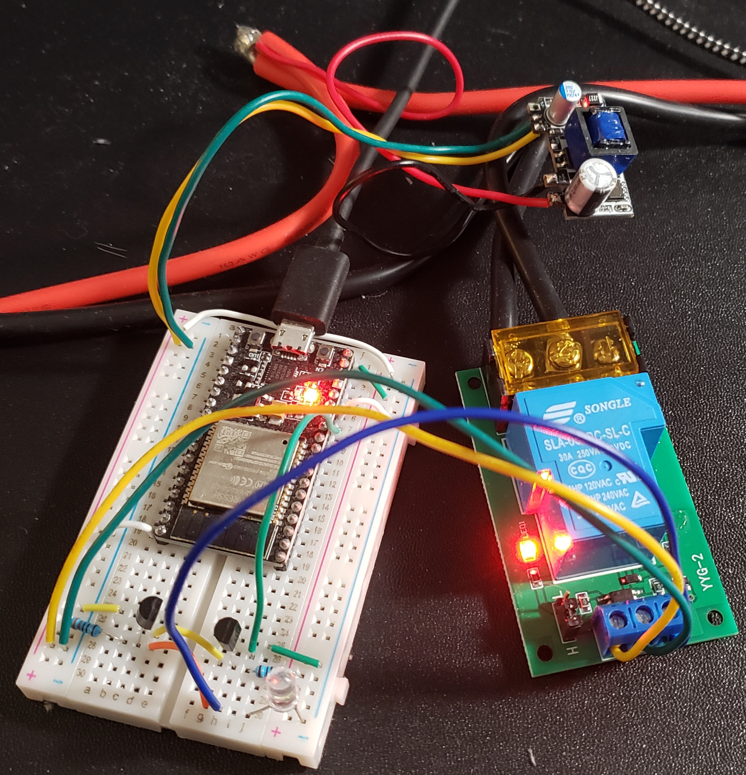
All of the hardware, pre-assembled. Here the devices are being powered over USB, which is connected to the ESP32 Dev module. In practice, the 5V regulator module (smallest board, connected to the larger mains wires) would provide power. The breadboard has a 5V level shifter made from NPN transistors to connect an ESP32 pin to the input terminal of the relay module.
The bulk of the device will be comprised of two modules, a microcontroller (MCU) and relay, both requiring power. Things like wires, transistors, LEDs, and breadboards I’ll leave as an exercise to the reader. In general, the exact parts are not super critical, as long as operating voltages match up. For anything carrying serious current, 10 AWG wire was used.
ESP32 MCU
The microcontroller units (MCU) are the intelligent parts of hardware, which can execute programs to perform actions. There are many options for microcontrollers in the wild, and the right choice is highly influenced by the type of connectivity needed. Connectivity could be to other hardware, where communication protocols like Ethernet, USB, HDMI, SPI, I2C, or even direct digital pins might be useful. Connectivity could also be to wireless networks, where integrated WiFi, Bluetooth, Zigbee, etc, would enable quick development. For smart devices, the integrated wireless network connectivity is critical, and MCU like the ESP32 excel in this domain.
Fortunately, one does not even have to deal with the bare part directly from the manufacturer, as these can require quite a bit of supporting hardware to be useful. These MCU typically will be available on “development boards”, like this one which can be found on Amazon or any electronics supplyer. Dev boards are excellent options for hobbyists, as they tend to integrate a USB-Serial interface along with power regulators, and other required infrastructure. The USB-Serial is especially critical, as it allows for communication with the running MCU and the capability to write a new program into its onboard memory easily.
For this project, the ESP32 is a bit overkill in its capabilities, but it’s a decently low cost one-size-fits-all platform for IoT devices. I’ll make use of one of the digital pins to control a relay, and the rest of its functionality will be implemented in software.
Relay
Mechanical relays, where a contact is closed with an electromagnet is energized, are perfect for doing the actual current switching. The only stipulation is that the relay opens wide enough to prevent arcing, and that its contacts are robust enough to handle the current we expect.
Some may advocate for solid state relays, arguing that they consume less current, have no moving parts, or similar. While there are applications where solid state relays make sense (high speed or rapid switching), the voltage drop across the load-side of such a relay means a lot of heat will need to be dissipated in high current applications. To avoid the complications of high temperatures, I’ll stick with the mechanical variety.
Like the dev board for the ESP32, its possible to get these bare devices mounted to small boards with all necessary supporting electronics. Something like this isolation relay module comes ready to connect to a 5V input signal. The ESP32 outputs 3.3V signals, but a simple level shifter with a few NPN transistors and resistors can easily solve that issue.
Power Supply
Literally anything that outputs 5V from AC input would work here. I found some simple modules that can output 1A @ 5V (and optionally has a 3.3V rail that I don’t need… right now). Both the ESP32 dev module (with its integrated 3.3V regulator) and the relay module can be powered directly with 5V.
Enclosure
As I recently obtained some 3D printers, it was only fitting to design a custom enclosure. Everything I’ve designed for printing so far has been done with Solvespace, so I went ahead with the same approach here.
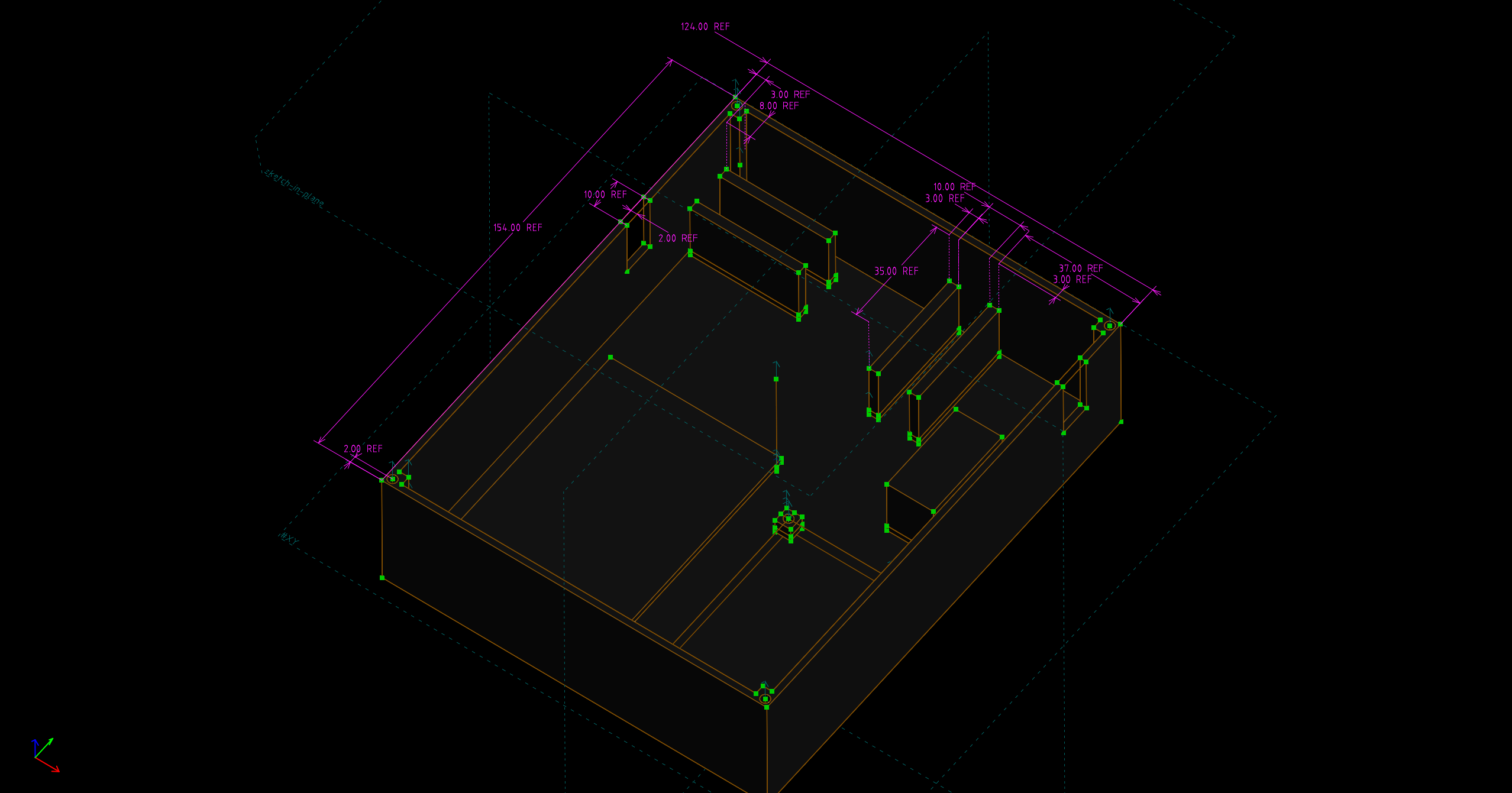
The final drawing for the base of the enclosure, with some reference dimensions for show.
Eventually, the omitted ground wire can be added as an extra hole in these replaceable tension-relief widgets that fit into the slots on the side of the enclosure base.
Many extrusions later, I arrived at the above. The layout is mostly inspired by the image earlier in this post, and how the materials compacted nicely together. I added some deep channels for the heavy wires, both to hold them in place, and to keep anything from getting near the soldered connections. Platforms for each of the other modules are included, even posts with screw holes for the relay module, because why not? The power module I plant to unceremoniously hot glue to it’s pedestal, while the breadboard comes with an adhesive pad on the back.
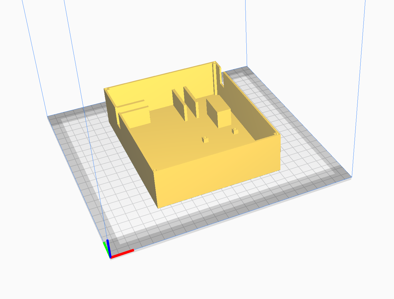
A rendering of the enclosure base in the Cura slicer.
Ultimately, these CAD drawings get exported as triangular meshes (STL files, models) that define the boundary of the object. This can then be imported by software more specific to 3D printing, known as a slicer. I use a slicer called Cura, though many (closely related) alternatives exist. The goal of the slicer is to decide exactly how to place extruded plastic down such that the shape of the model boundary is achieved. It has rules for how thick the boundary should be, as well as how dense and what style of infill should be inside the boundary. It can also generate structures to support areas that would otherwise be in midair - really slicers are remarkable pieces of software.
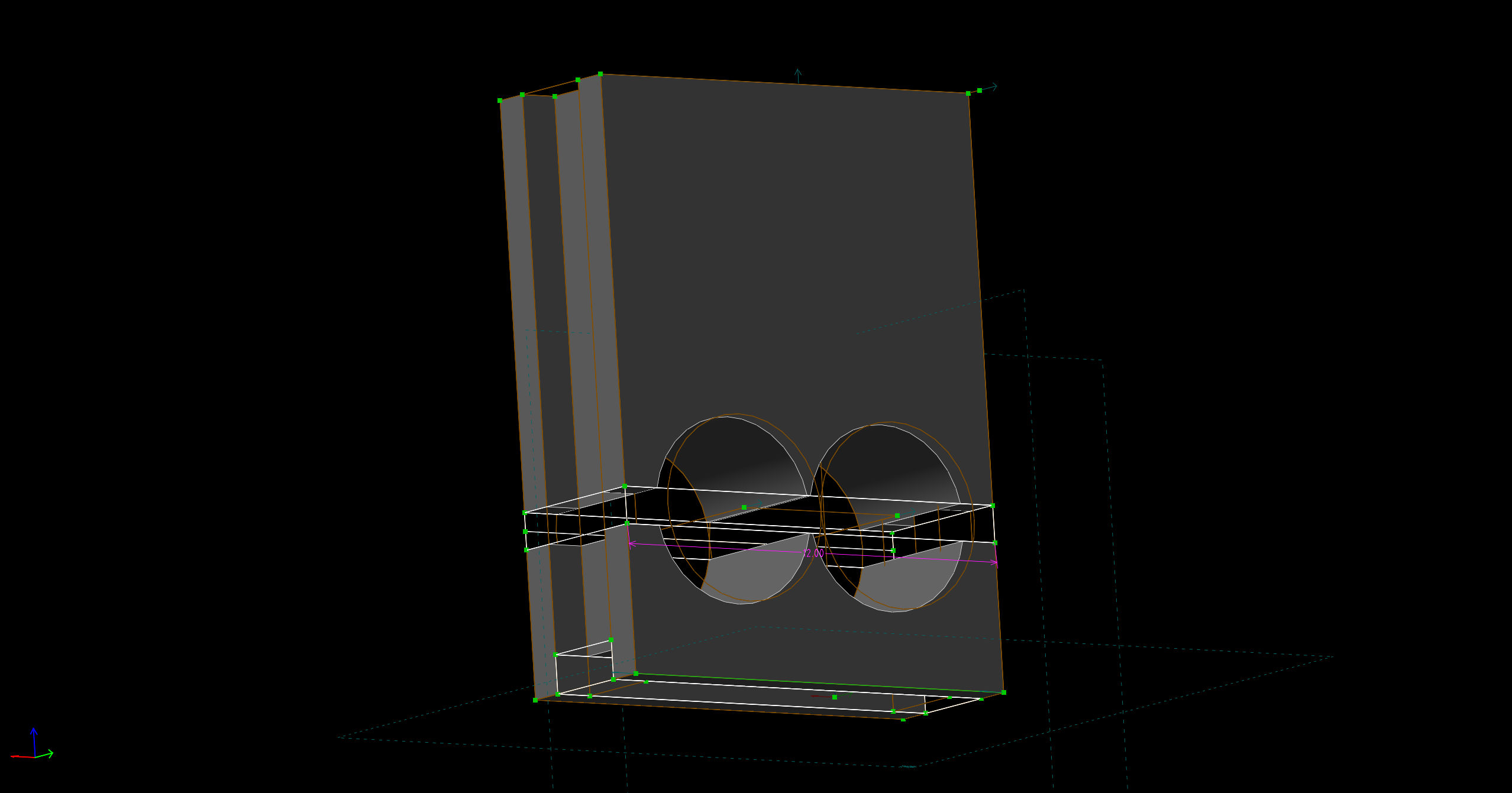
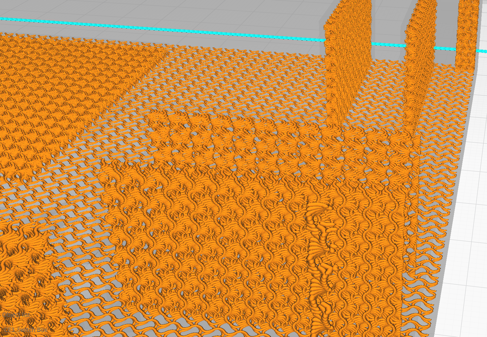
Cura can visualize the exact tool paths that are necessary to build the model, as shown in the next few screenshots. The green and red lines represent inner and outer walls, yellow is ‘roof’, and the more exotic looking orange lines are infill. Many patterns, styles, and sizes are configurable for these.
The tool paths of the exterior of the object, showing individual extrusion lines calculated by Cura. The same view as the right, but with exterior paths hidden, and the “gyroid” infill pattern (for structural integrity) left visible.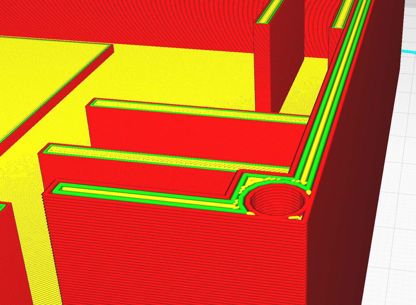
All that remained is to export the paths as GCODE, which is a language for describing how the extruding end of the 3D printer should move (and feed material) in 3D space to lay down those paths. The firmware that controls the stepper motors in the 3D printer gantry can read this GCODE and execute the motions. I printed this enclosure base with black PLA, and made a matching top with orange PLA.
Assembly
Since the enclosure was designed to fit these parts, everything went together nicely.
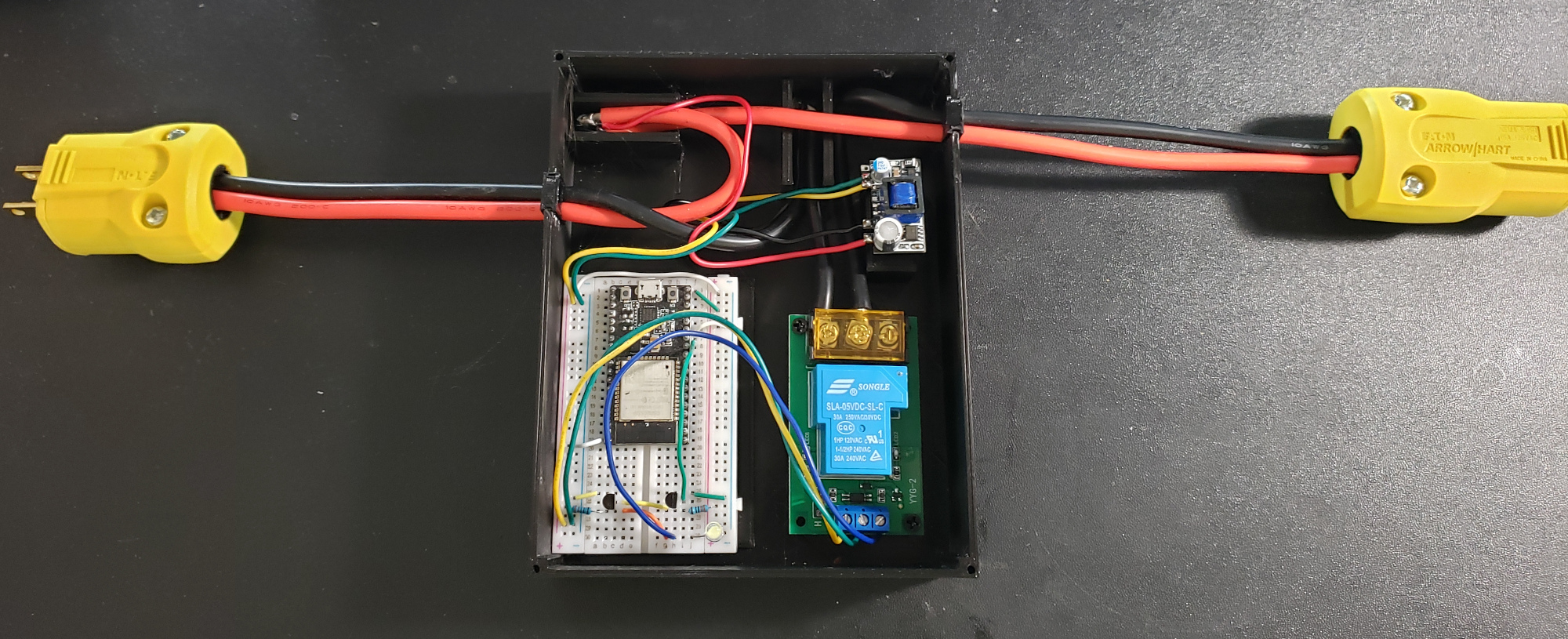
All of the hardware, assembled in an enclosure, with attachments to NEMA-15 plugs. These plugs will likely be upgraded.
To round it off, the lid has a grate and raised lettering showing the current rating, to look professional.
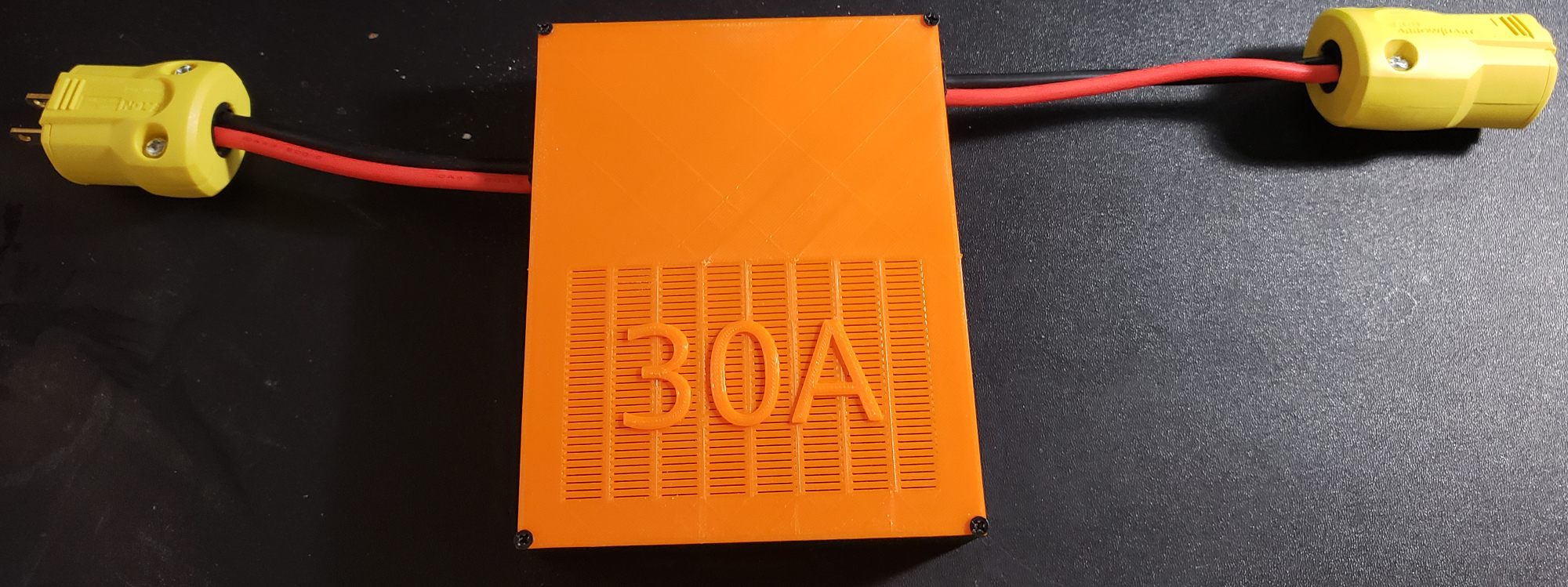
All of the hardware, in its final state. Not bad for a few hours, all things considered.
Software Details
With everything hooked up to the ESP32, all that’s left is to convince it to do something useful.
There are many software stacks for programming these devices, with varying levels of control and difficulty.
For something simple like this plug, I opted to use the Arduino-flavor tool chain, since it hides all the complexity of platform behind simple setup() and loop() entrypoints.
This makes the ESP32 more accessible to those familiar with the (significantly less-powerful) Arduino micro controllers, and enables very fast development.
Behind the scenes, Espressif has developed a proper bootloader that initializes the ESP32 and then schedules a task to invoke the loop() method on repeat.
This also includes a C++ API for interacting with all the hardware (WiFi, EEPROM, etc.) the ESP32 provides.
Connectivity
After including the WiFi.h header, a simple call to WiFi.begin("ssid","password") will attempt to connect, with DHCP, to the named network.
This does require knowing what network to connect to, and in lieu of hard coding it (as most examples do), the ESP32 platform provides a nice key:value store in its EEPROM, which will survive power cycles.
The key:value store is provided by the Preferences.h header and has pretty simple usage
Preferences prefs;

prefs.begin("credentials", true);
String SSID = prefs.getString("SSID","");
String PWD = prefs.getString("PWD","");
prefs.end();
where the second argument is the default, if the key was not found. Storing values is as easy as retrieving them.
prefs.begin("credentials", false);
prefs.putString("SSID",SSID);
prefs.putString("PWD",PWD);
prefs.end();
There will always be an initial state where no network info is known, or perhaps the network was unreachable, when the device can fall back to being its own access point.
WiFi.softAP("30AmpPlug", "30AmpPlug");
This will let any WiFi client connect (SSID: 30AmpPlug; PW: 30AmpPlug) and configure network settings.
Webserver
Communication with the smart plug will all be mediated by network requests, meaning something has to be listening on an open socket on the ESP32. The most common recipe in modern times is to have this program speak HTTP, the language of webservers. This will enable path-like access to resources (uniform resource locator - URL), which could be raw data, an HTML webpage, or some code that processes input data and produces a result, which gets sent back over the socket.
Once again, the ESP32 platform makes this trivial with a WebServer.h header, containing all the framework necessary for registering handler functions to particular resource paths.
The following sketch would send back OK with HTTP response code 200 when the path /sayok was requested.
WebServer server(80);

void handler() {
    server.send(200, "text/plain", "OK");
}

void setup() {
    server.on("/sayok", handler);
}

void loop() {
  server.handleClient();
}
At boot, the ESP32 will run the setup() method, attaching handler() to the /sayok resource.
Then, loop() will be called repeatedly, forever.
The handleClient() method will check for incoming network requests, determine the correct handler to invoke, and call it.
The entire program running on the smart plug is just an extension of the above, with some more intelligent endpoints. See the final software section for more details, but the handlers can, of course, return proper pages, allowing user interaction. Before I get to that, the next section shows how to add handlers that can interface with other software.
REST API
Home Assistant, or really any other modern automation software, is going to expect a REST API for any device it should control. In short, REST APIs are resources on a webserver (URLs) that can be used to instruct something on the webserver to take an action and reply. The commercial route is to provide a REST interface in the cloud, which your smart devices will connect to for instructions, and you can connect to in order to change the state of said device. The more-sane route is to put a REST interface on the device, and control it by connecting to it directly.
The RESTful Switch integration for Home Assistant works by default with any device implementing a very simple API: a single resource which:
- returns
ONorOFFin response to anHTTP GET - reacts to
ONorOFFin response to anHTTP POST
I’ve noted it’s polite to respond ok to POST just so the other end knows you received the message, and all of this is implemented in the api() handler.
void api() {
  ENTRY
  if (server.method() == HTTP_GET) {
    server.send(200, "text/plain", state ? "ON" : "OFF");
  } else if (server.method() == HTTP_POST) {
    if (server.hasArg("plain")) { //WebServer puts the body in "plain" to keep everyone confused...
      String new_state = server.arg("plain");
      if (new_state == "ON") {
        digitalWrite(RELAY, HIGH);
        state = true;
        server.send(200, "text/plain", "ok");
      } else if (new_state == "OFF") {
        digitalWrite(RELAY, LOW);
        state = false;
        server.send(200, "text/plain", "ok");
      } else {
        server.send(400, "text/plain", "");
      }
    } else {
      server.send(400, "text/plain", "");
    }
  } else {
    server.send(400, "text/plain", "");
  }
  EXIT
}
The Final Software
The software for the ESP32 is now available on my GitHub.
There you will find the additional resources I added to the server, including a configuration page for adding network credentials, and a root page that has an ON/OFF button for direct control.
These more-interactive resources generate HTML on the fly, and serve it up with the proper content type for browsers to load it like any other webpage.
Also present are the digitalWrite and associated setup to control the pin the relay is connected to, along with some code for indicator LEDs.
When the pin is “written” LOW or HIGH, the voltage level changes on the output, activating or deactivating whatever the pin is connected to.
To use this software, you would need an Arduino IDE and an ESP32 Dev board hooked up via USB-Serial for programming. You’ll also need to install the Espressif Arduino-ESP32 libraries. I include the entire code so it will be easy to use - this could be modified to control basically any hardware, or fit other interfaces.
Setup & Use
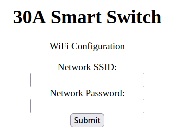
The /configure endpoint, which is configured to / when disconnected from WiFi and running as an AP.
If for any reason the software can’t connect to a WiFi network, it will fallback to being an access point of its own.
In this mode, a client can navigate to http://192.168.4.1/ to modify the WiFi configuration, rebooting the ESP32.
If it does connect, the plug control screen will be accessible at http://[dhcp_assigned_ip]/, as identifiable from the DHCP server’s logs.
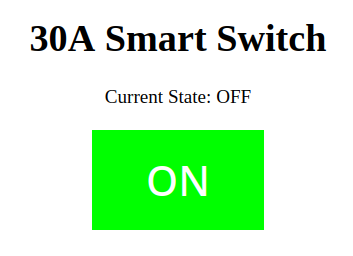
The / endpoint when the plug is off, ready to be turned on.
In the connected mode, the control screen will enable anyone on the local network the ability to turn the device on and off, as well as see its status.
For most home use cases, this is no issue, but if limiting access is a desire, additional logic in the software would be necessary.
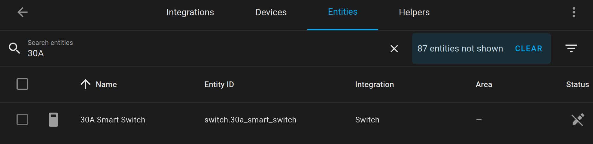
In addition to interactive control, http://[dhcp_assigned_ip]/api is a valid resource for the Home Assistant RESTful switch integration.
That integration will add this device to a Home Assistant instance, allowing automation, and everything else that ecosystem provides.
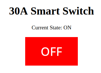
The / in the other state. I try not to think too hard about which one should be red or green.
If local control via a webpage is all that is desired, this is ready to use!
To tie it into Home Assistant, an addition to the configuration.yaml is needed:
 switch:
    - platform: rest
      resource: http://[dhcp_assigned_ip]/api
      device_class: switch
      name: 30A Smart Plug
Be sure to fill in the IP, set an appropriate name, restart Home Assistant, and you’re good to go!
The nearly instantaneous click from the relay when I click the icon with my mouse very satisfying.